

Do you hear that air? The click, the swoosh, the tsks, and the wisps all that comes from the air source on the manufacturing floor. It powers pneumatic actuators in assemblies and machines. Compressed air as the energy source for factory pneumatic actuators are produced by oil-lubricated air compressors. The air as produced contains oil, water, and machine dust, thus is not suitable to be used for the energy source for the equipment. It must be filtered for proper use in the pneumatic circuit.
Additionally, there is a significant distance of various plumbing connecting the air compressor and the actuators. Various other machines also share this compressed air over this distance and they mutually affect the air quality. The drive components for pneumatic components are becoming more complex and elaborate due to demands for miniaturization and cost reduction, often resulting in troubles caused by inadequate maintenance activities.
Factory Air Plumbing
The plumbing from the air compressor to the actuator end is classified into the following four sections.
1. Air Source Line
2. Main Line
3. Sub Line
4. Terminal Line
Air Quality
The air quality is classified based on the production line and products in which they are used for.
1. General Industrial Air
2. Precision Industrial Air
3. Clean Air
4. Precision Clean Air
5. Ultra Precision Clean Air
6. Medical Clean Air
Air quality is classified by the following parameters.
1. Quality of air (Foreign material types in compressed air)
2. Water and oil contents
3. Size of solid particles and removal rate
4. Odor
Air Quality Classifications and Clean Air System
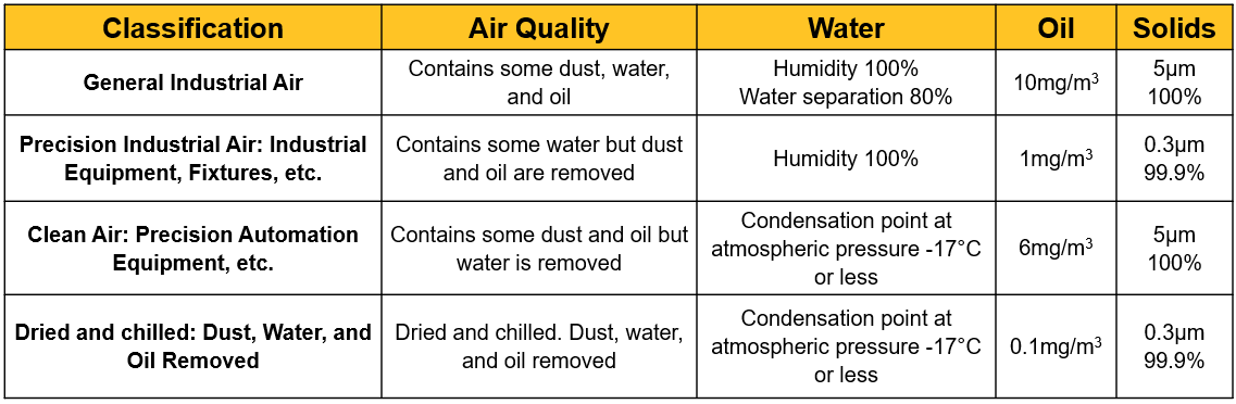
Condensation Point —Temperature point where water vapor containing air at a certain pressure becomes saturated and dew forms when cooled. Air dryness is evaluated with this index.
Example of a Clean Air System
Various filters shown below are placed at the four classified air supply lines, and air quality corresponding to each mechanical component is generated.

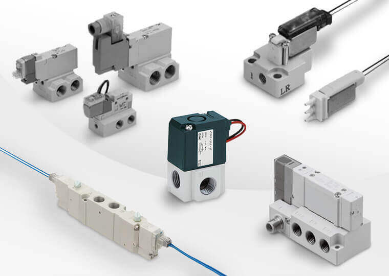
Pneumatic circuits and control technique basics are explained based on a scenario of the factory, lab, or manufacturing environment. There are a variety of components placed downstream to the air system such as air control devices including directional valves and velocity control valves, as well as pneumatic actuators (air cylinders, etc.).
Basic Pneumatic Circuit
A typical pneumatic device system is shown in [Fig.1].

The compressed air generation devices are located upstream to the Air Quality Control section, and the flow control devices and actuators are placed downstream of the Air Quality Control section.
The air pressure generally used is 7kgf/cm2 or less. The compressed air is cleaned of oil, water, and stored in the air tank, then further cleaned by the FRL (filter, regulator, and lubricator) unit, and supplied to the air cylinder through a regulator (pressure adjustment valve).
The system portion from the compressed air generator to the air quality control section is similar to the water service supply system. The waterline pressure is equivalent to air pressure. The actuator is driven by pressured air derived from the air quality control section which is analogous to a water faucet.
Symbol Description of Basic Air Circuits
The system in the [Fig.1] is described a compressed air circuit diagram using symbols. [Fig.2] below is a graphical symbol representation of the [Fig.1].

From the figures [Fig.1] and [Fig.2], it can be observed that easily and accurately describing compressed air device systems is possible by mastering the basics of compressed air symbols and air circuit diagram drawings.


Advantages of a pneumatic circuit are the ease of installation, cost, and maintenance. Pneumatic systems generally are compact in size producing more power in a smaller space. There are a variety of choices of actuators, filters, compressors, and valves to choose from so circuits can be simple or complex. It will always depend on the application parameters: output force and required speed.
If you need pneumatic components, MISUMI now carries Parker Pneumatic Components. Discover your next pneumatic success with their products!