
It seems like even the most basic engineering design decisions can be exceedingly difficult and complex. Almost every mechanical system involves some sort of hole/shaft joint, and an innumerable amount of diverse fits may be specified depending on each unique machine application.
Fortunately, equipped with the proper tools and armed with knowledge about standardized shaft and hole tolerances, the designer can build anything from interference fits for alignment pin setups to running clearance fits for journal bearing applications.
Clearance to Interference Fits
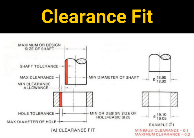
The first principle is the fit designation of the shaft/hole joint. The fit designation ranges from clearance fits to interference fits. A clearance fit specifies a fit where there will always be a gap in the joint between the mating shaft and hole. Even at the maximum shaft and minimum hole tolerance, the shaft will be able to freely pass through the mating hole.
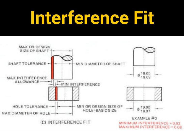
Conversely, an interference fit is a fit where there will always be overlap in the joint between the specified mating shaft/hole, even at the minimum material condition values allowed by the shaft and maximum value allowed by the hole tolerance values (i.e., the largest hole and the smallest shaft). This concept is illustrated in the figure below for both Clearance and Interference fits.
In between these two extremes are the “transition fits” where the specified tolerances of the hole and shaft allow for either an interference or clearance fit depending on the actual manufactured part sizes. There are other joint designations that exist as further subdivisions of the three main classifications: clearance, transition, and interference fits.
How to Determine Fit
After the basic definitions have been grasped, the designer should then be made aware of the general guidelines available to determine the classification of the fit for a desired application. If a must be able to slide or move in the joint, for applications such as a journal bearing mechanism, some type of clearance fit should be specified.
Conversely, an interference fit is probably required if relative motion of the shaft in the hole is prohibitive, the location of the shaft must be precisely controlled, the fit must be able to transfer weight, and/or the part does not need to be disassembled for maintenance purposes.
The transition fit might be employed somewhere in the middle of these two extremes, when a small amount of motion may be tolerated in the joint in order to better facilitate assembly and disassembly of the parts.
Specifying a Fit
The standardized nomenclature of the shaft/hole fittings differentiates between hole-basis and shaft-basis fits. The fits are two-digit letter/number designations where the hole basis fits are noted with a capital letter (H7) while the shaft basis fits are noted with a lower case letter (h7).
This is the most important concept to remember when sorting through the shaft/hole fit specifications. The second important concept to note is that fits can be specified using either a hole or a shaft as the primary reference basis. This means that fits can be specified from existing holes or shafts, which is important to know for design purposes, but in most instances, it’s up to the designer to decide how to build the joint from either a shaft or hole reference point.
The process of specifying a fit flows downhill from here; depending on the fit, there are various possible hole/shaft specification pairings. For example, using a H7 hole basis as a reference, a strong interference fit would utilize a t6 shaft specification. Therefore, the joint specification could be simply described as an H7t6 fit. Two summary tables for both hole and shaft reference fits are shown below to better illustrate the concept.

Figure 2: Commonly Used Fitting Table – Detailed fit tolerance tables, along with many more resources, are available via the MISUMI shaft product catalog. These resources provide the designer with everything that is needed in order to design a highly engineered fit for any application.
These number fit classifications are the key that unlocks the design tolerances of the fit. Each hole and shaft designation carries a required tolerance range depending on the nominal size of the hole and/or shaft. These two tolerance ranges, when taken together, completely characterize the fit and control the sizes of both the hole and shaft.
Conclusion
Although there is a lot more to be said about all of the various fit designations and the ideal times to employ each within different mechanical applications, this brief rundown of topics should provide the design engineer with enough understanding to begin working with the fit tables, specifying fits, and obtaining fit tolerance numbers for use in design tolerance and alignment studies.
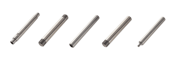
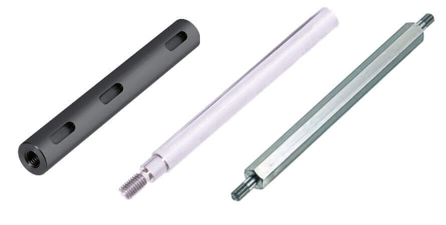
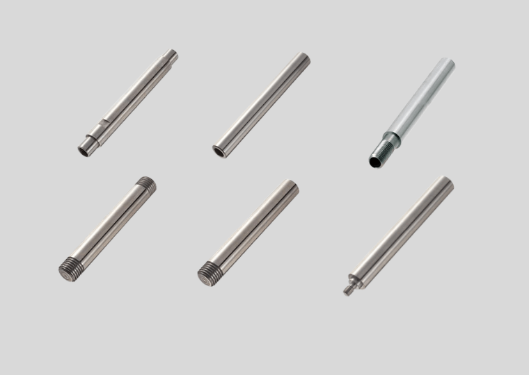
MISUMI offers a wide range of configurable linear shafts for your application.