
INTRO TO LINEAR GUIDES – LINEAR MOTION #1 | MECH MINUTES | MISUMI USA
In the latest series of “Mech Minutes”, we will take a deep dive into the world of linear motion technology and linear guides. We will discuss topics such as:
- Linear guide terminology
- Accuracy grades
- Preload and rigidity
- And more
Let’s start by reviewing the basic load definitions in linear guide technology.
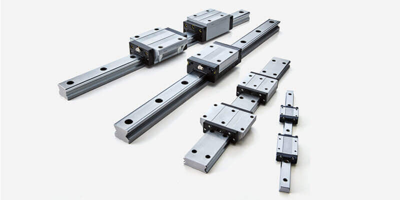
There are 3 basic types of loading that are considered for linear guide calculations; radial (or compressive) loads, reverse radial (or tensile) loads, and lateral (or horizontal) loads. Many linear guides are designed to handle all of these loading directions equally.
In addition to the pure directional loading, many linear guides are subjected to rotational or moment loads. While the ratings in the catalog may use a different letter depending on the manufacturer, the names of the moments are common across the industry.
The pitch moment is a tilting or rocking front to back along the axis of travel. Pitch moments are common during acceleration and deceleration. The next moment is the yaw moment. The yaw moment is a horizontal tilt or rocking side to side along the axis of travel. This would commonly result from off center lateral loading. The final moment is the roll moment. The roll moment is a vertical tilt or rocking side to side. This can be a result of lateral or radial loads, depending on the load locations.
Now that we understand the common load directions, lets discuss how linear guides are rated. The first rating is the basic static load rating (denoted C0). The basic static load rating is the maximum allowable load at any time on the system (moving or stationary).It is a measure of plastic or permanent deformation of the bearing element.
It is defined as permanent deformation equal to 1/10,000th of the rolling element diameter and is based on the materials used and the stress distribution on the ball or roller.
The second load rating is the basic dynamic load rating. Denoted as [C], it is a load applied to the linear guide at a constant magnitude and direction at which the nominal life of the linear guide is expected to be a fixed, given travel distance.
This travel distance is typically defined as 50 kilometers for ball type linear guides and 100 kilometers for roller type guides; however, this may vary by manufacturing region, so the designer should verify with the manufacturer when comparing linear guides.
In simpler terms, the basic dynamic load rating can be thought of as giving something of a benchmark for the expected life of a linear guide under a particular load [C]. Unlike the basic static load rating, the basic dynamic load rating may be exceeded, at the expense of service life.
It follows then, that the basic dynamic load rating can also be used to calculate the expected life of the linear guide system under a dynamic operational load.
For example, for a ball type linear guide, the 90% reliability service life parameter of the bearing, designated as [L10] can be calculated using a simple ratio of the Basic dynamic load rating [C] to the applied operational load [P] as follows.

It is important to note, that the basic dynamic load rating is a measure of fatigue.
Much like a paper clip being bent back and forth to the point of breaking, the material of the linear bearing block, rail, and balls can only handle so many cycles of loading and unloading before the material starts to flake away.
As a measure of fatigue, it does not directly account for temperatures, impact loads, lubrication, etc. although many manufacturers have correction factors that you can use for approximations.
The last set of ratings commonly found for linear guides are permissible moment ratings.
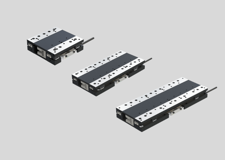
The permissible moment ratings in the catalogs are for moments applied to a single block on a single rail. They do not apply when using multiple blocks or rails in a system.
When a single block experience a moment, the load is unevenly disturbed among the bearing elements.The permissible moment rating is based on the loading for the worst case ball or roller. Some manufacturers include static moment rating for 2 blocks. This would only apply when the blocks are end to end.
As the blocks are spread further apart, the loading within each block evens out and the standard radial and reverse radial load calculations can be used.The standard rule of thumb for converting moment to equivalent radial and reverse radial loads without correction factors is 1 full block length between the blocks.
We hope you have enjoyed this journey through the loading terminology of linear guide technology.
Click below to view the video. Nothing like seeing linear guides in action!