
The applications using linear bushings are infinite. Where there is any linear movement a bushing can be used. Diving into more applications using linear bushings we will examine ball screw drives, air cylinder drives, and even a vertical guide. Looking at these applications may give us more inspiration for future designs and insight as to how linear bushings are applied.
Stepping Motors and Ball Screw Drive
The first application we will examine utilizes ball screws and a stepper motor. Ball screws provide good transmission efficiency and utilization of motor efficiency. They directly convert motor’s rotary motion into linear motion and the ball screw pitch works as a deceleration mechanism.
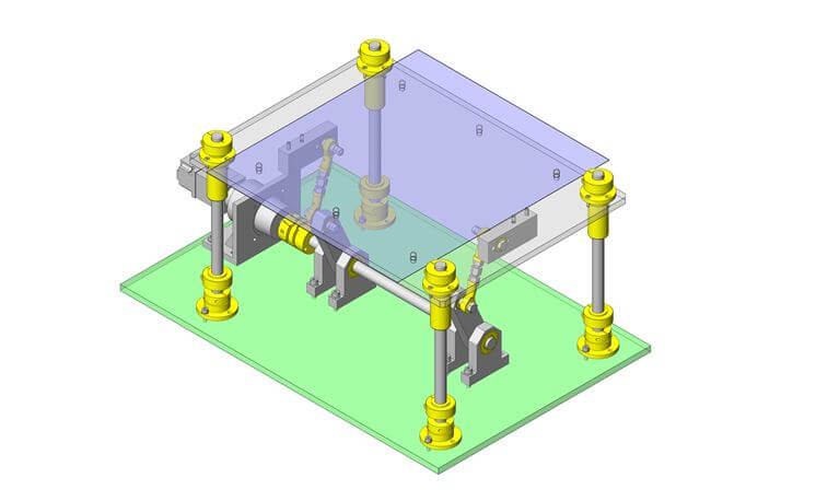
[Fig.4] below is a drive mechanism with ball bushings and a ball screw drive on the Y-axis, typically used where reduced cycle times and increased positioning accuracy are needed. The red arrows point to the location of the ball bushings, in this case, they are not easily seen but you can see the 2 guide shafts where the ball bushings would be incorporated.

| Supplementary Explanation
a) Stepping Motor Characteristics b) Required Motor Accuracy to Achieve Targeted Positioning Accuracy |
![]()
Air Cylinder Drive
[Fig.5] below is clamp mechanism driven by an air cylinder on a guide bearing. [Photo 2] also below is a magnetically coupled air cylinder mechanism. They both use linear bushings highlighted by the red arrows. These bushings allow for less friction in the cylinders movement and also provide rotation prevention.
Since the air cylinders cannot be velocity controlled during acceleration and deceleration, shock absorbers are used to reduce the shocks when stopping ([Photo 2]).

Vertical Guide Examples with Flanged Linear Bushings
Flanged linear bushings are used in a variety of vertical guide applications for its ease in mounting and compact size. They can be mounted securely on a vertical guide without special holding devices, allowing for a compact and simple mechanism. Photo 3 shows that a vertical base plate is needed on the slide guide to stabilize the rail. The linear bushings are highlighted by the red arrows.
Photo 4 shows them used as elevation guides from the lower parts of transfer conveyors, highlighted by the red arrows. Photo 6 shows a conveyor example with linear bushings on the shafts. Figure 7 shows them in a locating mechanism, all highlighted by the red arrows.


If you would like to see more application examples using linear bushings, check out inCAD Library, the Misumi Application Library. Search “Linear Bushings” and it will render many applications that use linear bushings! All applications are free to download and available in many 3D CAD platforms. This concludes the series on Working with Linear Bushings!